
Robotic Palletizers: Payload, Reach and Cycle Time Calculations
Evaluate robotic palletizers using tool-plus-case payload, reachable approach and exit motions, and cases per minute calculated from a stated handling cycle.
Updated October 19, 2026: Initial publication of the payload, reach and cycle-time calculations.

An arm that lifts a case can still miss the top pallet corner or fall behind the infeed. Evaluate robotic palletizers by checking payload with the tool attached, reach through the complete handling path, and cycle time converted into cases per minute for that stated motion.
Start with the handling envelope
Define the case, tooling and pallet arrangement before comparing arms. A useful proposal identifies the following inputs and the evidence needed to accept them.
| Input | Required basis | Failure mode and prevention |
|---|---|---|
| Loaded tool mass | Complete tool plus all cases and carried accessories | Overloaded configuration; account for every carried component |
| Combined center of gravity and inertia | Mass distribution relative to the flange in loaded and empty states | Motion restrictions or reduced acceleration; verify the OEM load envelope |
| Placement envelope | Every layer, corner, approach and exit with the actual tool | Unreachable motion or collision; review the complete programmed path |
| Handling cycle | Pick, confirmation, transfer, release and return boundaries | Understated time; include tool actions and waits |
| Cell interruptions | Sheet handling, pallet exchange and fault recovery | Shortfall over the production period; account for non-overlapping interruptions |
Use the robotic palletizing systems guide to define the surrounding cell, and the palletizing index to connect this calculation to load design and downstream handling.
Payload includes the tool and every case being carried
Loaded payload is the sum of the complete flange-mounted tool and its carried load. Universal Robots’ maximum-payload note explicitly includes the gripper and workpiece. It also relates permitted loading to center-of-gravity offset and describes the effect of payload configuration on acceleration.
Formula: Mloaded = Mtool + n × Mcase + Mother.
Masses are in kilograms; n is the number of cases carried together. Mtool includes the adapter and carried tool equipment; Mother covers any additional carried item, such as a sheet, without counting anything twice. Use the configuration-specific OEM limits for center of gravity and inertia as well as mass.
Worked mass example — editorial assumptions dated October 19, 2026: A complete single-case tool of 8 kg carrying a 12 kg case, with no additional carried item, gives Mloaded = 8 kg + 1 case × 12 kg/case = 20 kg. A different, assumed layer tool of 14 kg carrying a complete 4-case layer of the same cases gives 14 kg + 4 cases × 12 kg/case = 62 kg. These inputs describe hypothetical handling concepts, not named robot capabilities.
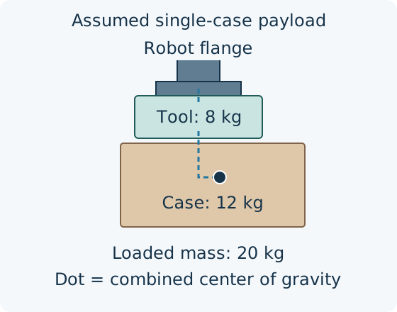
Single-case mass example. The combined center of gravity includes the tool and case; its marked position is schematic and has no assigned offset dimension.
Threshold rule: If Mallowed − Mloaded is less than 0 kg for the required pose and load configuration, choose a lighter tool, a smaller pick group or a robot configuration with sufficient permitted capacity, because the carried mass exceeds that configuration’s limit. Passing this mass screen still requires the center-of-gravity, inertia and motion checks.
Confirm the tool’s grip on representative filled cases separately. The gripper-selection guide addresses the package contact conditions that mass arithmetic cannot resolve.
Reach covers approach, placement and withdrawal
A reachable placement point is only part of the required motion. Check the pickup, loaded transfer, approach above the stack, placement and withdrawal using the intended tool center point and case envelope.
The OEM palletizing template defines separate approach, tool-action and exit waypoints. This provides a useful review boundary: each must work at the relevant layer and item location. The following path is an editorial schematic of that distinction.
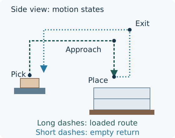
Motion boundaries, not a robot reach plot. Dashed routes distinguish the loaded approach and empty withdrawal; the entire tool and case envelope needs clearance.
Review the highest and furthest placements, the lowest placement near pallet hardware, and the path beside adjacent stacks or guards. Include tool orientation, routing of carried utilities and the actual pallet datum. A nominal reach dimension does not describe these clearances or prove that a particular joint configuration can execute the route.
Convert the stated handling motion into cases per minute
Calculate the cycle from one repeatable state to the next identical state. Here that state is the tool ready to start a pickup, with product already presented. The cycle ends when the empty tool has returned ready for the next pickup.
Formula: Tcycle = Tpick + Ttransfer + Trelease + Treturn + Twait; Qideal = 60 s/min × n cases/cycle ÷ Tcycle s/cycle.
Times include the approach, lift and settle motions assigned to each segment. Twait covers additional waits outside those segments. The conversion factor 60 s/min is the unit definition, not a performance assumption.
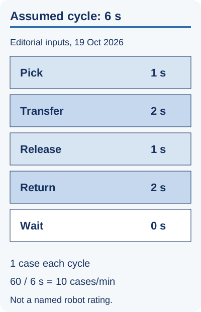
Assumed single-case durations from this page, dated October 19, 2026. Not a robot rating.
Worked motion example — editorial assumptions dated October 19, 2026: The durations below are selected arithmetic inputs. No travel speed or robot model is inferred from them. The layer concept carries the entire assumed 4-case layer in one trip; its layer is ready before pickup begins.
| Motion segment | Single-case pick | Prepared layer pick |
|---|---|---|
| Approach pickup, grip, confirm and lift | 1 s/cycle | 2 s/cycle |
| Loaded travel and placement approach | 2 s/cycle | 3 s/cycle |
| Set down, release and confirm | 1 s/cycle | 1 s/cycle |
| Empty withdrawal and return | 2 s/cycle | 2 s/cycle |
| Additional wait in this initial assumption | 0 s/cycle | 0 s/cycle |
| Total cycle time | 6 s/cycle | 8 s/cycle |
| Cases carried | 1 case/cycle | 4 cases/cycle |
| Calculated repetitive rate | 60 × 1 ÷ 6 = 10 cases/min | 60 × 4 ÷ 8 = 30 cases/min |
This comparison is arithmetic, conditional on those durations and complete groups being available. It does not establish a general speed advantage for layer picking. Under an additional assumed 4 s/cycle of non-overlapping layer-formation wait, the layer result becomes 60 s/min × 4 cases/cycle ÷ (8 + 4) s/cycle = 20 cases/min. If formation overlaps robot travel, count only the remaining wait; adding both full durations would double-count concurrent time.
The mass example also shows the associated change in carried load: the assumed layer concept requires 62 kg, compared with 20 kg for the single-case concept. A valid comparison must first find configurations that can handle their respective tools and loads throughout the required paths.
Account for the time and hardware outside the repeated trip
The hidden cost of a larger pick group can be the upstream equipment needed to collect, orient and present that group, plus recovery when a case is missing or damaged. Include accumulation space, recipe changeover and the consequences of stopping that equipment in the cell cost review.
Sheet insertion, pallet exchange and downstream blockage can also reduce production-period output. Use the live throughput calculation guide to connect repetitive case rate to available running time. Keep the repeated-trip calculation, group-formation timing and production-period interruptions as explicit inputs so that an attractive arm cycle does not conceal an infeed or pallet-handling bottleneck.
Method and source scope
The saved OEM notes establish the payload components and palletizing waypoint distinctions. All mass and duration inputs above are editorial assumptions dated October 19, 2026; the formulas show how to replace them with the proposed tool data and a timed or simulated project sequence. No brochure production rate is reproduced. Sources checked October 19, 2026.
Sources and scope
Source dates refer to the material consulted, not independent performance verification.
- Universal Robots: Maximum Payload
Payload includes gripper and workpiece; center-of-gravity offset and inertia affect permitted motion and acceleration; no robot ratings reproduced
UR30 online manual, PolyScope X 10.8 · Checked October 19, 2026 - Universal Robots: Palletizing
Palletizing sequences include approach, tool-action and exit waypoints, layer patterns and optional separators; used for motion boundaries, not production speeds
PolyScope 5.20 online manual · Checked October 19, 2026
Published by DeltaSpark. Editorial policy · Corrections and contact
Continue reading
How to Select a Palletizing Gripper for Your Products
Compare vacuum, side-contact and support-based gripping concepts using packaging samples, tool loading, access and repeatable trial records.
Read articlePalletizing Throughput: Estimating Capacity Without Confusing It with Robot Speed
Calculate palletizing capacity from picks, cycle time, pallet exchange and stated downtime assumptions, with a worked example and sensitivity table.
Read articleRobotic Palletizing Systems: Types, Components and Selection Criteria
Define a complete robotic palletizing cell, compare handling concepts, and collect the product, pallet and interface data needed for a proposal.
Read article